E46 keyfobs
My fault
Well, my diamond shaped keyfob started becoming unreliable. I spotted it becoming unreliable in one of the 3 functions that they key performs. The central locking started to become intermittent – sometimes it would work. Giving the key a shake would improve things. In the ignition it always started the car, though sometimes there was a bit of a delay which i assumed was normal. The mechanical part of the key locked and unlocked the doors fine.
Diagnosis
There are quite a few guides out there on key faults, but none really covered my fault. The central locking button in the car worked fine, and the windows went up and down, and the interior lights came on so it wasn’t the GM5 relay problem (symptoms are the lights coming on but the doors don’t unlock). It had been working fine, and i hadn’t been tampering recently with other systems, so knew something had started intermittenly failing.
Disassembling the key
OK, so this is tricky, and many people get it wrong. I’ve taken it apart twice now, and both times i have scraped components off the PCB. The factory key is untrasonically welded together, which melts plastic to plastic. So, you need to carefully cut through the plastic. The tricky think is that it’s once you’ve been cutting at it for 5 minutes, slowly applying more and more pressure that you cut throgh the last part of the seal and straight into the components. Here’s a picture of a cut open key so we can discuss doing it carefully:
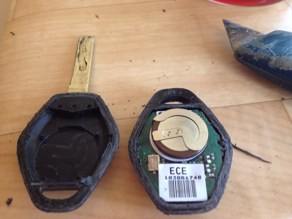
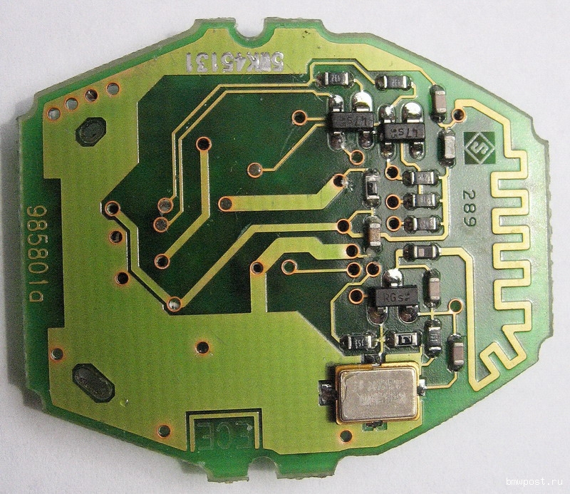
In the picture on the right, the PCB can be seen in the same plane as the cut line, which is why it is so easy to slice the components. The top of the key has been rotated 180 degrees from the base in this picture. The most likely place you will slice through the components is when your knife is cutting down from the metal part of the key. This is the area that needs most care. Once cut through this area, you can then do the 2 sides, and then cut through the end last. At the end, you only risk hitting the battery which you are less likely to damage. Take care!
Inside the key
So, my fault was that one of the two battery terminals had a broken, dry joint. You will need a microscope to inspect the solder joints on the PCB because they are so small, using something like 10x to 20x magnification and a nice bright light. I measured the battery on a mutimeter, and it was measuring 3.0V which is still enough for normal operation. You might want to replace it if it is lower than 3 volts – there is a section on that below. You might also want to check if the voltage collapses when you push the battery into the PCB – this is another common fault as the paper pad underneath the battery wears over time and then shorts against tracks. The fix to this is some kapton tape applied underneath the battery: Kapton Tape
Replacing the batery
So, you need to buy the right “battery”. On ebay you will see batteries for sale for an e46 key, and these will have the same terminal carrier arrangement as shown in the picture above if they are the right battery. If the legs are in different places in the locations where they fit into the PCB, you will be ripping them off and re-soldering them which is best avoided. Check the voltage across the terminals with a multi-meter before considering fitting it. You will need a soldering iron with a reasonable tip. Insert a spudger to create force between the batter and the PCB. With a soldering iron at about 250 degrees heat up the solder contact on the PCB. Once molten, the spudger will separate the battery and PCB. Repeat this process until the battery leg exits the PCB. Do not force the battery leg and PCB apart if the solder joint is not molten. Repeat for the other leg, and the battery will come off the PCB. Now you can heat up the remaining solder in the through hold PCB and flick the board wit your fingernail to get the solder out the hole. Checking the polarity, solder the new battery down.
Fuck it, i cut off some components getting it open
I hear you. You were warned. I’ve been here twice. It’s not irrecoverable, depending on what you broke. But you will need that microsocope, some fine tweezers, replacement components, some fine solder, and a fine soldering iron. You will need some experience with soldering, because working at this level (0603 components) is not all that easy to get a good joint. You are working with RF circuits and you will need to get the right component accurately onto the footprint. You probably can’t get away with re-using damaged components, even if they look ok to the eye, it’s possible to damage the internal joints from the package to the many internal layers. I suggest you review the damage on the microscope and decide if you want to take your chances.
Firstly you need to remove anything left that is still damaged. Pads that look clean will still have the bottom of the removed component present, so heat up the pad with the soldering iron, and away will come the part of the component that is still left. You may spot at this point that you have damaged a track, an if so you will have to improvise with some fine gauge strand cable to re-connect the damage. With fairly clean pads, you are ready to put the component back. Apply a tiny piece of solder to the iron to wet it. Place the component on the pads and hold in place with tweezers. Apply the wetted iron to one pad. Remove and confirm the component is correctly positioned. Re-heat that one pad and re-seat if needed. Once accurately placed, you can repeat the process on the other pads. Try not to heat things up for any longer than needed, especially because the circuit is live the whole time, which means you should try and keep components only where they should be to avoid a short curcuit.
But what are all the components?
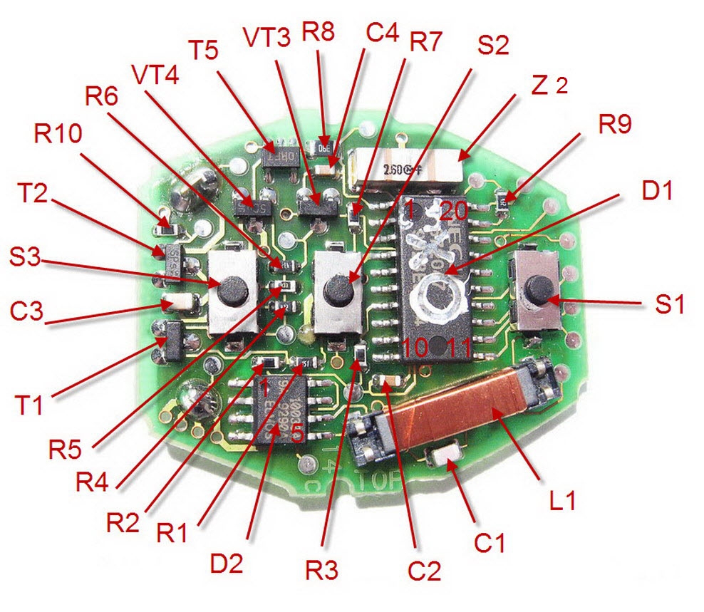
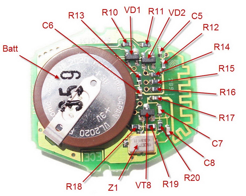
Here are some schematics for you from a Russian website, plus values for identified components:
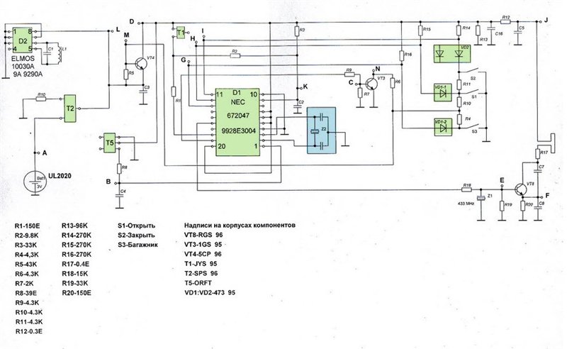
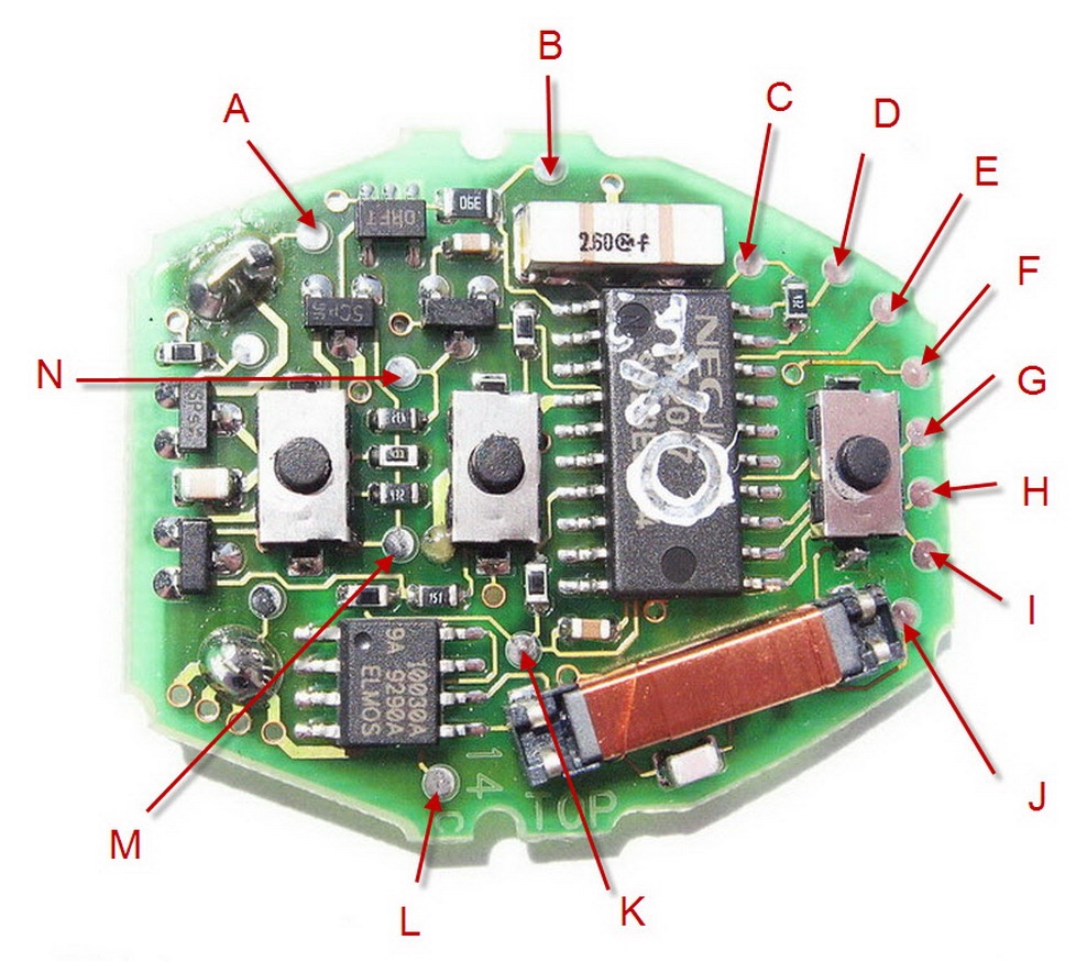
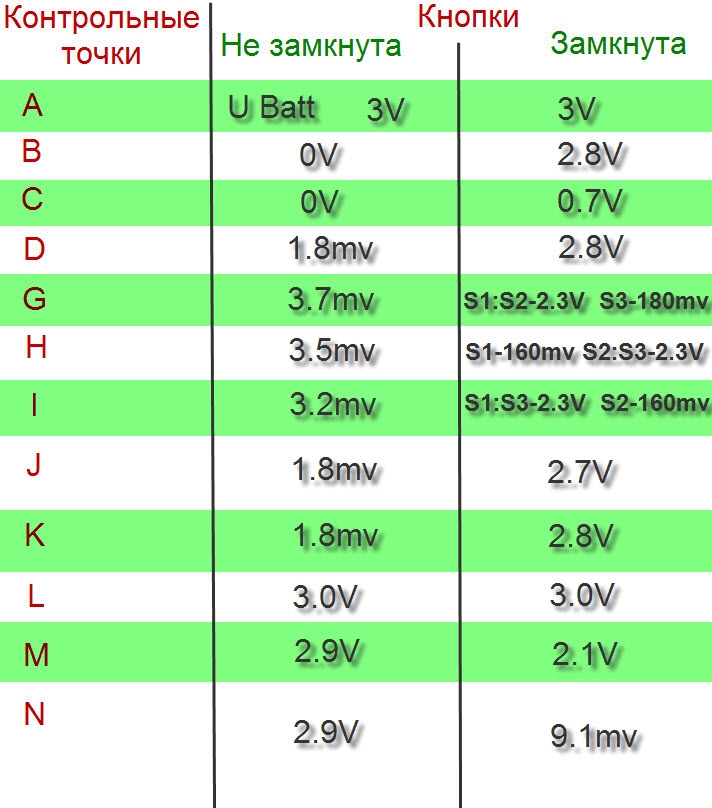
In case your scientific russian is not up to scratch, those titles read “Test Point” “Button not pressed” “Button pressed”
From what other information i can gather for a 433MHz variant, the following components are suitable replacements on the PCB. Bear in mind that some RF components may be a little different for the 315MHz version used in the US. Sizes are imperial e.g. 0603 is 1.6mm x 0.8mm. Some components you can’t buy new, so best to buy another used key of ebay an swap over.
Too hard?
All too tricky, here are you options?
1. Hello BMW… £150 per key (prices Nov 2018 Southapton BMW), no further discount available.
2. Find someone who will fix it for you. There are some key repair services out there, but i have no idea who is competent. Take your chances.
3. Buy one off ebay from someone who can code it up. Components will be grey market, so probably won’t last long, but hey. Beware of scams like giving someone access to your EWS immobilier secret codes plus your home address, or it’s bye-bye car. Insurance won’t cover you if they had a key…
4. Buy the bits off ebay and code it yourself. This requires: key cutting (a trip to town), immobiliser programming (see section below), plus central locking synchronisation sequence (see section below)
Immobiliser programming
So, i bought an AK90+ of ebay. Here’s the link to the one i bought.
I paid a bit more for an item located in the UK so that it arrived quickly. Most were cheaper and located in China.
The instructions state that it should be run from Windows XP. As i was going to be connecting my EWS and i didn’t want to break it, i decided to follow the instructions instead of chancing it on Windows 10. So, i downloaded virtualbox from here selecting both the windows hosts and VirtualBox Extension Pack which you need to allow USB devices to be connected.
You then need to Run virtualbox and configure a windows XP machine – instructions here on how to achieve this. My recommendation is to select a VHD file of fixed size (e.g. 2Gb) so that you can mount the VHD file into windows 10 later on and copy files on and off of it easily. I would also recommend in your vitualbox configuration that you disable your network card from being passed through to prevent any nasties getting in and out of your vitualbox.
Next, you need drivers for both windows 10 and windows XP for the serial to USB converter that is part of the AK90+. Download them here . Install the windows 10 ones on your normal PC. In windows 10 start your Computer Management tool (Search from start menu search), and select Disk Management. In the menu select Action-> Attach VHD and select your windows XP HDD. In my computer, browse to the attached HDD and copy the windows XP drivers for the AK90+ to the disk. Go back to my computer, right click on the mounted VHD and select eject. Connect the AK90 to your computer. Start your Virtualbox. Navigate to the directory you put the drivers in. Install the drivers. Go back to the virtualbox menu and in the menu select the option to connect a USB device. Select the CP2102 device and your windows XP installation will detect new hardware and install it. Next, insert the AK90 CD into your CD drive. In your virtualbox menu, connect the CD drive to your hosted windows XP installation. Run the installer for windows XP. At the end of this step, you will have the setup ready to use.
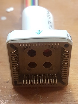
Your AK90+ will have a cable with a square socket on the end. This needs to be correctly oriented to the chip when it gets connected otherwise it will probably blow up your EWS. Helpfully, mine didn’t have it’s orientation marked, so i had to work it out myself. They are normally marked with a red dot or green arrow as shown in the image below. If you look really carefully on the underside of the socket there is a corner symbol and hole in the 4 corners, so you can mark yours up as well if it also is lacking in markings.
Next, i checked that the EWS was working with my final working key. You may or may not have this privalage. I do not recommend reading an unused key just in case that prevents it from being written to later. Keys are single write memory. In windows XP, load the AK90, and put your old key in the reader. Click “Test Key” in the AK90. It will read the key and present information back on it. It will probably be a Key number in the range 1 to 4. It shoud display your VIN correctly. It should read the mileage in km correctly. If this works then you know that your AK 90+ is working. Read and other keys you have and note down the numbers for later.
There are reports out there that the AK90+ needs to have the key positioned at the right height in order to guarentee writing to it. So i decided to modify my AK90 so that the key sat in the hole better. I unscrewed the 4 screws underneath, and carefully lifted the 2 halfs of the case apart until the end of the stops. Be really careful doing this beause the fine wire used to connect the writing coil to the PCB is very fine wire, and if you pull the two halves apart too far you will break the wire and need to repair it. With the 2 halves apart, the key sits at the right height in the wire loop for the coil on the key (L1 in the components identified above). Check the key still reads correctly.
Next you need to get your EWS out the car and read it. Here’s a video on EWS removal. Open the plastic package clip, and pull out the PCB. The big integrated circuit (an MCU) is the one that the AK90+ adaptor fits over. You’ll need to read the part number off it, and make sure you get this right otherwise you’ll blow it up. Mine was an OD46J. You’ll need to scrape the legs gently with a flat bladed screwdriver to get the conformal coating off the pins. It’s probably a COSHH controlled substance, so i recommend you take appropriate precautions. Following the image that can be seen in the AK90+ programe by clicking the EWS Picture button, plug the AK90+ adaptor over the integrated circuit. Load the AK90+ programme, and select the matching MCU to your part. Again, get the right one or it will blow up. Click the Read ECU button. It will make lots of binging noises and give you reading progress. If it fails, it’s probably because the pins aren’t making good enough contact, so check you scraped it well, reseat the socket and hold it to the PCB firmly (the force you would need to hold a piece of toast without crushing it), and click read again until it reads. Once read, you will get a dialog asking you to save it. Save it somewhere safe and secure – it holds all the info you need to program keys to start your car. You wouldn’t want it getting nicked, and since i have distrust for Chinese software, that is why i told you to disconnect the network card earlier. You can now disconnect your EWS and put it back in your car – you don’t need to write to it. You’ll have noted earlier the key numbers you have already. The EWS also tells you which keys are enabled by clicking on the analyse EWS button. Typically keys 1-4 are enabled. At this point you do have 2 options. You can either write your new key back to one of the unused slots (however this doesn’t protect you from previous owners using the key they still have to nick your car), or you can re-use an old slot. To re-use an old slot, put a key into the AK90+, at the right height as noted earlier, and click Write Key, select one of the unused slots that you don’t have a key for (as before, normally 1 to 4), select the right transponder in key (either PCF7930/35 or 10030A) and click write key. Whoever sold you the key should know what type it is. If you need to work it out yourself then open the key up, and look at whether Z1 looks like a copper colour or is just a solid black lump. Copper is 10030A. Black is PCF. This takes 30 seconds to write. Once written, click test key and check it reads back propery. If you want to enable a new key, I believe you will need to click enable key in the Analyse EWS dialog, and then write the modified EWS data back to the EWS using the write EWS button. I haven’t done this, and it will carry risk because if you write garbage back to the EWS because a pin dowsn’t work, you may brick it and need a new EWS. If you give it a go, and for example enable key 5, write to the EWS and then write to key number 5, you can do it this way. Test the key again by reading it back and checking the VIN and key number is right. Keys can only be written once, so don’t try re-using them!
Put the EWS back in the car, and check your keys start the car
Key Cutting
You need to find somwhere that will cut your key blank. This can be challenging. I tried using Timpsons, but they didn’t want to know, despite them not telling you clearly on their web page that they will refuse to cut customer provided blanks. In the end, after trying about 5 shops in Southampton, I went to AutoTechnix who have a laser scanner to read the key, and a CNC milling machine to do the cutting. 10 Minutes and £10+VAT later, and my key was ready and working.
Remote central locking sync
Do the following:
1. Unlock your car and sit in the drivers seat then lock the doors (locking the doors isn’t important it also works if they’re unlocked but its easier to watch the doors pins later)
2. Put your key in the ignition
3. Turn your key to the 1st position briefly just so you see the mileage until service light come up (or whatever it is that your bottom middle box on the dashboard displays) then turn off and remove key. You need only do this once, you can do it more than once for your own preference but it doesn’t matter once is enough. Also it doesn’t matter if you leave it on in the 1st position for 1second or 10 seconds as long as the process of turning it to 1st postion and off again removing the key has been completed.
4. Press and hold the door unlock button and whilst doing that press the door lock button 3 times then release the unlock button, as soon as you release that unlock button the door pins will shoot up and back down again or if it was unlocked then they go down then back up again it doesn’t really matter it’s just a sign to tell you that the programming was successful. If you have a second key then don’t repeat step 3 just pick up the other key as soon as those door pins have shot up and down and do the same as you did with the first key. Hold the door unlock button and press the lock button 3 times then let go of the door unlock button and the door pins will shoot up and down again. You have to do this for all they keys you own one after another, or otherwise they will no longer provide central unlocking.

My key fob doesn’t work.
I checked all voltages and all of them match except for Testpoint B when buttons are pressed and C when buttons are pressed there is no voltage.
Any idea how this can be fixed?
LikeLike
Check voltages L, M, D and J to check that power is getting to the circuits B and C. Trace from the battery onwards, you probably have a broken track or component somewhere you can find
LikeLike
Hello, I have a problem with a E46 keyfob that transmits 250-350Mhz instead of 433Mhz (it must be 433Mhz). I have already replaced the SAW resonator and 433Mhz filter, along other components.
I see that test point B only tests 2.5 or 2.6V, not 2.8V. I have a donor key which works and also outputs 2.8V on pad B.
LikeLike
simply swap the two 8pin chip between the two remote…. works like a charm
LikeLike
For the operating frequency, keys come in 433 Mhz (Europe/Aus/NZ) and 315 MHz (Japan/USA) options, and your car will receive the same frequency. If it’s meant to be 433 MHz and operating at 315 MHz then the likely culprit is Z2 which sets the frequency the device transmits at. I suggest you swap Z2 from a donor key? Z1 is then an RF saw filter which will remove unwanted frequencies.
For pad B if the voltage is low then it is probably an issue with T5, R8 or C4. You could take those parts from the donor key. It’s more likely its T5 or C4 that has failed, a faulty C4 would give a series resistance that could pull the voltage down, T5 could do anything if it fails, an R8 failure would more likely go short/open circuit than change resistance.
I would personally get it working at the right frequency before seeing if the test point B voltage makes any difference – depending on the function of that port a few hundred millivolts may not make much of a difference.
LikeLike
Thank you so much for your reply! I have just swapped all components mentioned (also Z1 and Z2 to be sure) but unfortunately it doesn’t make a real difference. I do notice that the frequency no longer seems to float, it is mostly a constant a 265Mhz now.
LikeLike
Hello, so tried replacing the battery my self, unsuccessfully since I ripped the battery + pad on the IC side. I managed to merge the A point and Battery connection with a solder blob and made 2 small wire connections to the T2 Mosfet, looked fine apart testing point J. Looked more closely at the board and it seems I managed to knock off “R”12 inductor… I can’t get any less then 100pcs of them when I’m living (buying of Ebay is the same as getting those 100pcs). My question is, do it have to be specifically “that” inductor that you linked or can it be any 22nH inductor? or even more stupid question can I just bridge the contacts?
LikeLike
It looks like it’s part of a final stage pi filter before the antenna, so it will be a low pass filter removing high frequency spurious. Can probably bridge the pins and it would work but may interfere with other nearby devices when using the buttons!
LikeLike
Hmmm. Well it’s not like they are always pressed, so it shouldn’t cause any issues or effect it’s performance, right? And what using other 22nH inductors? Like with current rating at 500mA?
LikeLike
I suspect 500mA is overkill, the key is probably only a few milli watt output and not on much of a duty cycle, so 500mA 22nH 0603 will probably be fine.
LikeLike
Hey, I started fixing my fob since it wasn’t working for quite a while and I’m not sure where to start… Slim to none testing points matched the given ones. Here are mine:
a 3 3
b 0 0
c 0 0
d 1.5m 1.43
g 2.7m s1:s2-0.99V s3-0.2V
h 2.7m s3:s2-0.99V s1-0.2V
i 2.7m s1:s3-0.99V s2-0.2V
j 1.5m 1.41
k 1.5m 1.42
l 2.5 1.43
m 2.5 0.83V
n 2.5 0.83V
Everything seems fine visually. Could it be R10 on the IC side? It measured 94.2kOhms and somehow manages to let through ~0.6V. Any recommendations what should I do? Any help would be appreciated!
LikeLike
Your supply voltage, L is collapsing when you press a button. Probably a knackered or discharged battery.
LikeLike
Before buying a new battery, can I test it with 2 AAA batteries or would that be an overkill, since they measure 3.2V in series?
LikeLike
Good idea, should be fine to test it with.
LikeLike
Sorry, seems my replies haven’t been submitted, even after trying 4 times… (sorry if it spams, I get no notification if the comment has been submitted or anything similar). I tried with 2 AAA batteries, they measured 3.14V, point L was 2.82V and after pressing the button it still dropped to 1.8V…
LikeLike
Most likely now that something downstream of the power supply is drawing too much current and something is current limiting or something in the supply line has a fault and is limiting current supply too much.
LikeLike
Hey! Thank you for the information. I had to replace R12, R17, and C5 on my keyfob. I ordered R12 and R17 with the given values, but the key didn’t work. I ended up going for 10uH for R12, 22nH for R17 and 1pF for C5. (My key is 433MHz.) Now the key is working perfectly
LikeLike
Thanks for contributing with the updated values!
LikeLike
Hey on testpoint b when not pressing any button i got 2.3v and when pressed it goes to 2.8v sometimes i can lock the car but 2 other buttons do nothing i only changed the battery do i need to sync central locking?
LikeLike
Hi Jacob,
If it locks sometimes then it is properly synchronised – if it was not synchronised then it would never work.
Test point b should read 0v when not pressed, so suggests there is a problem with the main IC not properly working with the output from the dcdc chip.
You most likely need a new key
Best
Simon
LikeLike
I just unknowingly knocked off c5 and r10 (battery side). Went to the car and managed to get the immobiliser reprogramming to work. But the car only locks with the key. Doesn’t unlock or open the boot. And now when I stick the key in the door to unlock all the doors, the key only manually unlocks the drivers door. When I open the door the alarm sounds. But when i turn the key in the ignition the alarm turns back off again. Car starts and drives fine. What’s my best course of action? Many thanks
LikeLike